SPIDEY
Made with Fahad Iqbal, Humzah Iqbal and Mir Hamza | Year: 2014
Took charge of 555 timer circuit, tripod algorithm and coding micro-controller
A robot capable of mimicking the three-legged walk of arachnid insects.
Made for a course called "Digital Logic Circuits" with Prof. Anwar Zaidi in Karachi, Pakistan.
Chosen as one of 10 showcased projects at the World Space Week celebrations organised by the Pakistan Space & Upper Atmosphere Research Commission (SUPARCO) at PAF Museum, 2014.
Tools: 8051 Micro-controller, PCB design and production, DC Servo Motors, ROM, Acrylic fabrication

The aim of this project was to create a robot capable of moving forward on its own in a straight line, using an even number of legs on each side.
The challenge was, to mimic natural movements of a spider (or any arthropod insect) which has eight jointed legs. We needed to engineer a movement which takes into account the physics of biology, and we needed to use the knee as a propeller, like real spiders do.

A well thought-out combination of servo motors, comparators, multiplexers with an
alternating tripod logic circuit at the centre made us successfully accomplish our
goals.
The project is thus divided into the following parts:
-
A clock circuit with a 555 timer
-
Which signals to a micro-controller circuit that outputs a pulse-width modulated wave (duty cycle)
-
Calibration of displacement and storage of data in a ROM
-
A multiplexer circuits with complex branching of AND and OR gates which signal to servo motors for alternate leg movement
Circuitry

The clock circuit consisted of LM555, a microchip capable of producing a simple square wave with a combination of resistors and capacitors.
The output was something like this (where N is the frequency of the power source, Vcc, shown as a red line):

Building on the clock circuit, we made following circuit to create a Pulse-Width Modulated wave, which would serve as a binary signal for the robot's legs.

We did several experiments with servo motors connected to power, and used the following formulae in order to calculate the duty cycle required in our PWM (pulse-width modulation) - it is the proportion of 'on' time to the regular interval or 'period' of time; a low duty cycle corresponds to low power, because the power is off for most of the time.
(D, the duty cycle in the following formulae, is expressed in percent, 100% being fully on.)


The resulting wave:

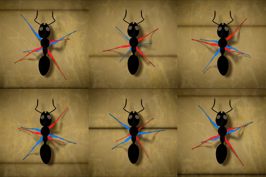
While the others took responsibility of the hardware, I devoted my energy to the implementation of the tripod algorithm of locomotion, the entire program stored in a ROM. I did so by treating the six legs of the spider as two independent sets of tripods. For each leg, the position and velocity were calculated using calibrated sensors which in turn determined whether the leg was in support phase (equilibrium/reference state) or transfer state (on the verge of state change e.g. leg on the ground but about to be lifted).
This classification developed the basis for the special section algorithm that put similar state legs in one category, passing on a signal to the servomotor, for their synchronised movement:

Robot body

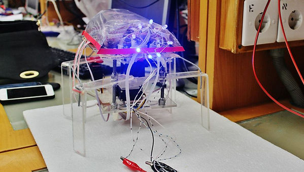
The body was fabricated using laser-cut transparent acrylic, moulded at the knee joint and for the dome which held the circuits together.
I soldered a little LED ring for aesthetic purposes.
Showcasing

